Simulator motion control
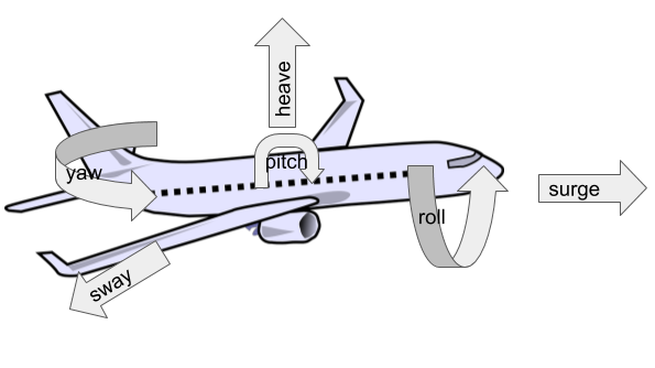 In this post I’m going to explain the motion control software. This software takes game data and generates motion commands to the actuators. It also provides very basic visual feedback via a GUI and control via the keyboard. The game data is in the form of rotational orientation about the three axis (roll, pitch, yaw) and three translational accelerations (heave, sway, surge). The motion commands are in the form of a length for each of the six linear actuators that move the platform relative to the base.
All of the code is available on github.
Game data
The game data comes from XPlane via the UDP interface. The source code on github also contains code to use the TCP interface of the NoLimits2 rollercoaster simulator.
Stewart platform
The simulator itself is a Stewart platform which is used on commercial full-motion flight simulators and a variety of other devices/robots that need to control position with six degrees of freedom. The Stewart platform has a triangular base and platform, connected by six actuators that vary in length. The actuators are connected by universal and/or rose joints so that changing the length of the actuators moves the platform relative to the base. To drive the platform, we need to compute the desired position of the platform relative to the base (both translation and rotation) and then compute the lengths of each of the actuators.
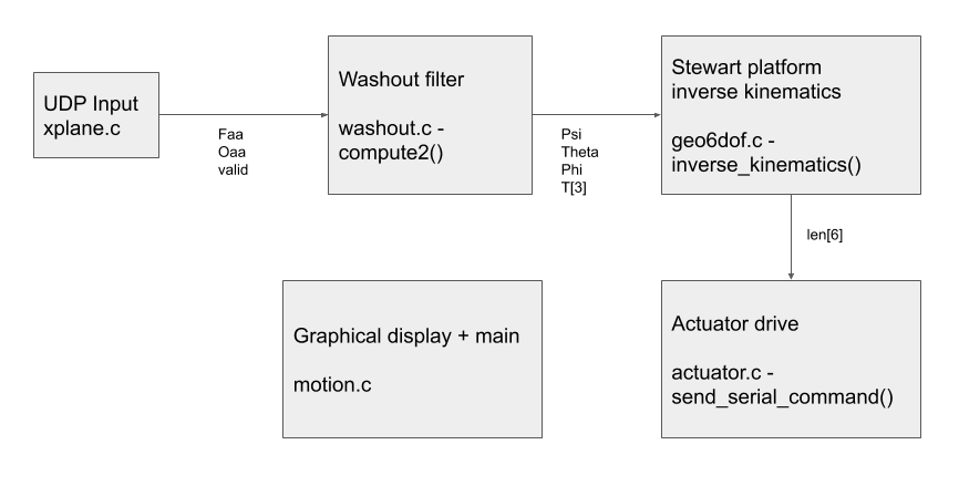
The below figure shows the structure of the code on github. The washout filter computes the desired position of the platform and the inverse kinematics computes the length of each actuator.
Classical motion cueing
The motion cueing algorithm exploits limitations in the human ability to perceive motion to simulate a fast-moving aircraft within the constrained physical motion of the platform. Our senses have evolved to handle only (survivable) human generated motion, which is apparently why non instrument-trained pilots who stray into cloud and try to use these senses rapidly lose control and crash.
This Reid-Nahon paper goes into great detail including models of the human perception system and various alternative drive algorithms. I also found this PhD Thesis to be a useful reference.
While the theory is complex, the so-called ‘classical’ algorithm is actually quite intuitive:
The translational accelerations are both high-pass and low-pass filtered (a bit like the crossover in a loudspeaker).
The high pass filtered output directly drives the platform. The low-frequency components are not actually perceptible and not directly enacting them means the actuators return to their central position between motions.
The low pass components are instead used to tilt the platform, using the gravity vector to simulate them. For example; a constant acceleration forwards causes the platform to roll backwards, effectively pushing you back in your seat. If you can’t observe the roll (the horizon stays in the same place on the screen) and the speed is below the human threshold for perception, this creates the illusion of constant acceleration.
The rotational components are also high-pass filtered and summed with the platform tilt. All of the high frequency components need to be rotated by the ‘fake’ tilt to keep everything in sync.
Digital filters
Reid and Nahon use Laplace notation to describe the transfer functions (the relationship between the input and the output) of the various filters in the classical algorithm. Laplace notation describes a filter that operates in continuous time (a physical system such as mechanical dampers, springs or analogue components like capacitors and inductors). However, we want to build a filter that operates in discrete time since all our inputs and outputs are samples of the game forces at some time interval.
In the digital, discrete time world what we need is an IIR (infinite impulse response) filter.
The IIR filter sums together a finite number of previous inputs and a finite number of previous outputs, each scaled by a coefficient. To find the coefficients we need a bit of maths called the bilinear z-transform. I have no idea how this works (I was probably supposed to learn it at some stage), but the mechanics of it is to substitute in an equation containing z for every s, and multiply everything out until you have a polynomial in z. The coefficents of the polynomial become your filter coefficients. Multiplying by z delays by one timestep, so multiplying the input or output by z means take the previous input/output, by z2 means two timesteps ago and so on.
For example, the code in fc_hipass_2 implements the first order high-pass filter described in the Reid/Nahon paper.
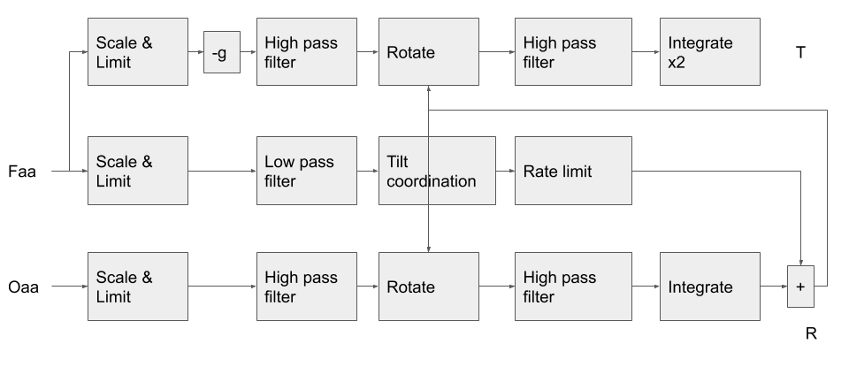
The function compute2() in washout.c implements the classical motion cueing algorithm. It takes as parameters the 6DOF aircraft forces and generates desired position of the platform
The below figure shows the structure of the compute2 function.