A dead-end
In the previous post I described how to use a microcontroller to adapt the LCD signals from a 30 year old gameboy to drive a modern LCD screen. While it can be made to work, it’s ultimately a dead-end. Pipelining allowed us to keep up with the gameboy but what I really want is upscaling to fill the LCD screen. This doubles the number of pixels in each line that have to be sent to the LCD in the horizontal dimension (to go from 160 to 320) and in the vertical dimension we’ll occasionally have to send two lines (to go from 144 to 240). While there might be a way forward by looking at a different microcontroller, or trying to drive the 16-bit parallel interface on the LCD, ultimately I had an itch to build some custom hardware, so that’s where we’re going.
From software to hardware
Hardware and software both get described using high-level languages these days. The verilog language (which I chose for this project) even has a passing similarity to C. If you’re moving from the software to the hardware world, I think that similarity is more misleading than it is useful. The mental model for the C program described in the previous post is that some sort of processor (a Turing machine) goes through our program line by line and carries out the instructions in order.
That’s not how hardware description languages work. There is no control flow, each line of your code is causing a new piece of hardware to be generated, that runs in parallel to all the other bits of hardware in the system. One analogy is desiging a clock. The software description for a clock increments the second, tests if we need to increment the minute, checks if the alarm needs to go off, draws the hands in the new position. In the hardware description of the clock, each line of code generates another bit of clockwork and all of the clockwork runs together, at the same time.
Even more confusing, there is a way of making each line of your verilog run ‘in order’ but it’s ‘non synthesizable’ (meaning: can’t be compiled into actual hardware) and so you use it for writing testbenches that exercise your design to see if it works.
I’m not going to write a tutorial here but I strongly recommend fpga4fun. What I would say to someone coming from the software world is, forget everything you know, nothing that looks familiar will actually help you.
Of course, there is a way for hardware to do a list of things in sequence, and decide what to do next based on what happened in the past. The way to do that is construct a finite state machine. To solve the gameboy interface problem requires building several.
A finite state machine has three components:
- A register, which stores the current state
- A function that maps the current state and the inputs to the next state
- A function that maps the current state (and optionally, the inputs) to the output
The state can be whatever we want it to be. An ‘enum’ tends to be quite useful, or an integer value. Of course, it all boils down to some binary bits. Like clockwork, it runs on a tick. Every tick the next state becomes the current state and the cycle repeats.
It’s worth pointing out, in the software world, the computer is just a really complicated state machine, where the current state includes all the data in memory.
Complete design
The complete design has several state machines all working together
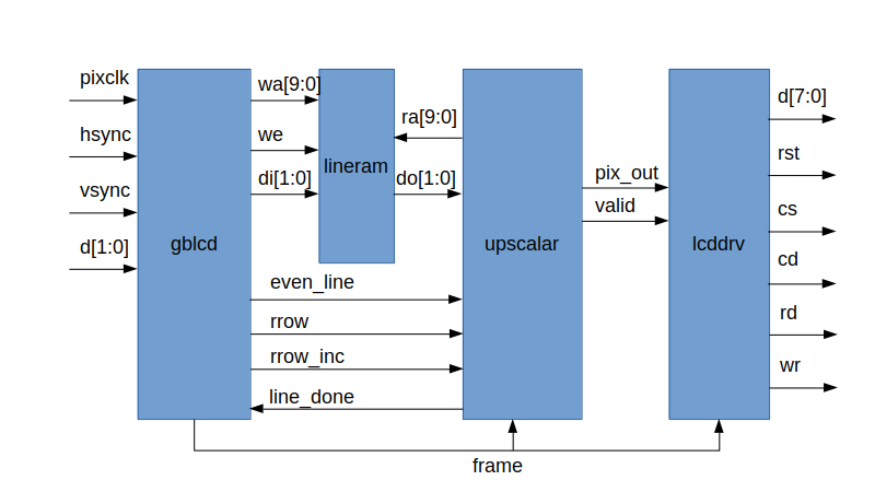
- gblcd captures the gameboy signals in the local clock domain and contains a bunch of counters to track the position of incoming data in the frame.
- lineram is just a RAM that buffers four lines of 160 pixels.
- upscalar does pixel art upscaling from the gameboy 160x144 resolution to the LCD 320x240.
- lcddrv sends an initialization sequence to the LCD and then writes pixel data.
Please bear in mind if you look at the code… this isn’t supposed to be a masterclass in hardware design. I do this on my own time for my own amusement and that means cutting corners.
Capture
Continuing the clockwork analogy, sometimes you end up with multiple sources of time. In this case, the gameboy generates a 4MHz pixel clock which is not free running (it ticks for every pixel, then stops) and not fast enough for our purposes. So what we do is generate our own free-running clock and synchronize all of the data to it. Transitioning clock domains is a can of worms because of a phenomenon called metastability. Basically the clock ticks can align in such a way that the output of your circuit is unpredictable. At this point we could descend into theory about setup/hold times but instead I’m just going to describe the engineering solution which is to put all inputs through two stages of registers in the destination clock domain. This makes metastability rare enough that it’s basically never going to happen.
To transfer the pixel clock into the new clock domain, a simple state machine generates a toggle on each clock. This toggle gets synchronised (with a double register) into the new clock and each toggle indicates a new pixel. This is a useful trick to make sure every clock in the source domain is counted exactly once in the destination. The clock, together with the hsync and vsync then drives a series of counters: a column counter that counts every pixel and a row counter that counts every 160 pixel row. There is some extra logic to fill and flush the pipeline… as we’ll see later the upscalar runs two lines behind the input.
Upscaling
I implemented the simplest pixel art algorithm on wikipedia: scale2x. Scale2x converts every pixel into four ‘upscaled’ subpixels using four of the adjacent pixels. The way that I do this is to buffer four lines of the incoming frame into a RAM. At any one time three lines are being read and the other is being written. I do four separate reads for every pixel… the other adjacent pixel is just a delayed cersion of the central pixel. Could I do all four reads in parallel? Is it possible to avoid reading the central pixel and use a delayed version of the leading pixel? Yes to both, but it takes eight cycles to write a pixel to the display so I’ve got time to spare.
The diagram below shows how the buffer is used for upscaling. Pixel data is continually being written to the RAM, wrapping every four lines. The upscalar follows two lines behind, reading the tile of four pixels.
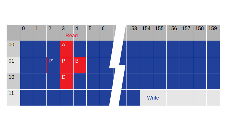
For horizontal scaling, I simply output both pixels to go from 160 to 320. For vertical scaling, I output both rows of pixels except for 1/3 of the lines, where I just output one. This gives the required upscaling from 144 to 240 (144/3 = 48, 48x2+48x2+48 = 240).
Below an example before/after (before on the left!). The image on the right was generated by the Verilog testbench.


Driving the LCD
To initialise the LCD we need to send a carefully timed sequence of commands. An efficient way to do this is build a little microcoded processor that runs through a set of instructions in ROM. The ROM is a giant case statement that maps an address to the data stored in ROM. The processor has a 10 bit instruction. The most significant two bits are an opcode and the remaining 8 bits an immediate value.
| Opcode | Instruction |
|---|---|
| 00 | send 8-bit immediate value to LCD as data |
| 01 | send 8-bit immediate value to LCD as command |
| 10 | delay for 8-bit immediate value of cycles |
| 11 | stop (and wait for pixel data to write) |
It’s a multi-cycle processor - performing fetch, decode and execute (the execute stage itself can take multiple cycles) in sequence. Simple, efficient and plenty fast enough for our needs.
The result
Not bad! Full screen with hardware upscaling! The FPGA board is a Xilinx Spartan-3 sample board that I begged off one of the sales people when I worked there (I asked if there was an employee discount scheme for FPGAs, and they gave me ‘that look’). The gameboy logic signals are 5V, which the Spartan-3 can cope with if you limit the current with series resistors (visible in the photo). The gold USB cable in view is just providing power for the system. The other box is the programming cable used to send the confiuration to the FPGA.
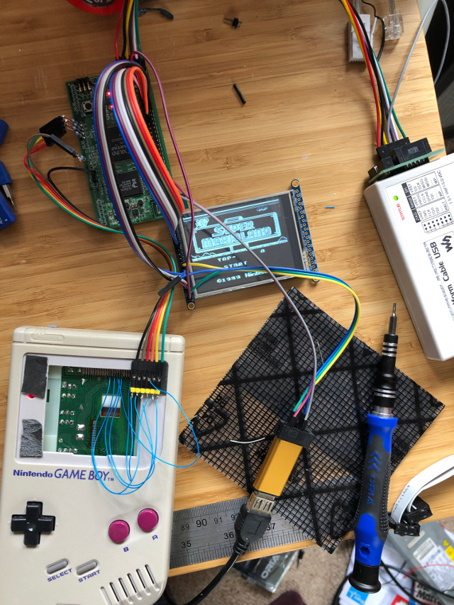
Not exactly portable though… it’s a long way off fitting into the original gameboy case and doesn’t run off the gameboy batteries. I’ve a funny feeling this isn’t the end of the project!