Calibrating the MAF
As described in the previous post, the MAF and the AFM both measure airflow into an engine and output a corresponding voltage into the ECU. The AFM measures volume flow and the MAF measures MAF flow.
To emulate the AFM with the MAF, we need to determine the voltage generated by both devices at a range of air flow rates. To do this, I built the simple flow bench in the photo below:
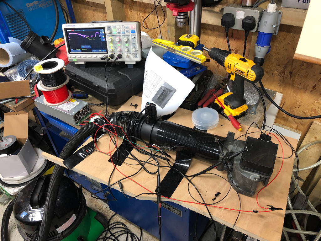
The AFM and the MAF are connected in series with a silicone hose and the output of each wired to a channel of the oscilloscope. I’m using a vacuum cleaner to suck the same amount of air (mass and volume!) past both. I found I could vary the flow by disconnecting the hose from the vacuum and opening up a gap. I wasn’t able to max out either the AFM or MAF with the Henry vacuum. I tried our Dyson as well which was comprehensively out-sucked!
AFM vs MAF Output
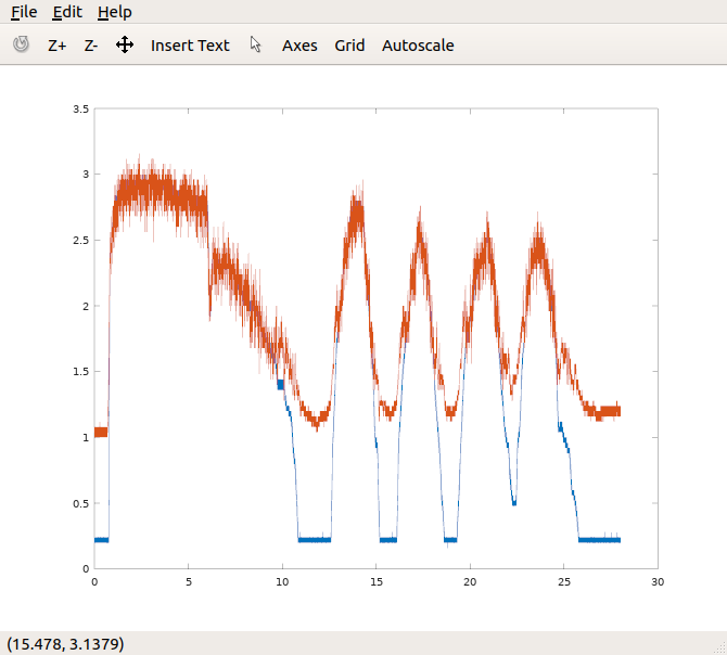
I set the scope to capture 700k samples at a 200us interval, so just over two minutes with various different levels of airflow. You can see the raw capture below that clearly shows the different voltages from the two sensors (Y axis is in volts). Note that the MAF (orange trace) is relatively noisy because as a solid-state device it responds quickly to airflow changes.
Cleaning up the data
To clean up the data I used GNU Octave (a free clone of Matlab). The scope saves captures as a CSV file, so I wrote this function to read in the two channels as arrays.
function [t,ch1,ch2,sample] = readdat(file)
	data = dlmread(file, ',')
	len=size(data)(1)
	t = data(13:len,1)
	ch1 = data(13:len,2)
	ch2 = data(13:len,3)
	sample=data(14)(1)
endfunction
I then low pass filter both of the channels:
pkg load signal
[t,ch1,ch2,sample] = readdat(file)
freq = 1
nyquist=(1/sample)/2
[b,a]=butter(2,freq/nyquist)

ch2filt=filter(b,a,ch2)
ch1filt=filter(b,a,ch1)
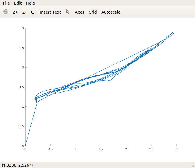
Then scatter plot the two channels against each other:
scatter(ch1filt,ch2filt, 1)
Which looks like this:
Now to build some hardware…
So now we have the map between the MAF and AFM signal (at a given temperature), the next step is to build a circuit that takes the MAF input, looks up what the AFM would generate and then outputs the correct voltage. I’m going to leave that for another post…