Emulating the AFM
The original 944 AFM has a spring loaded flap which the intake air pushes against. The higher the air flow the more the flap is pushed back against the spring. This flap is mechanically coupled to a potentiometer that divides the voltage supplied by the DME according to the flap position and hence the air flow (volume, not mass). The voltage supplied by the DME to the potentiometer varies by model year, the early 944’s having a higher voltage vs the later models.
To calculate the amount of fuel to inject, the DME needs air mass flow which can be calculated from volume and temperature using the ideal gas law. To enable this, the AFM has an inbuilt thermistor that changes resistance according to the air temperature.
The MAF outputs a voltage between 0 and 5V depending on the mass flow. So what is needed is a way to translate this signal to the equivalent AFM output voltage.
Circuit explained
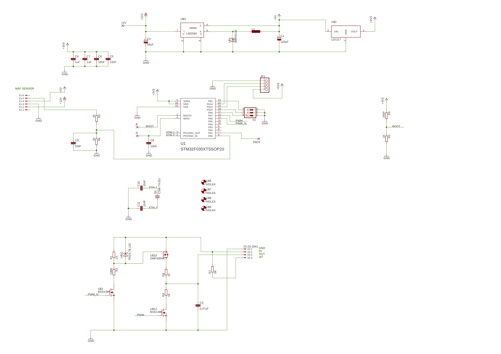 The design is centred around U1, an STM32F030 Cortex-M0 based microcontroller. These are gloriously simple to use, I used this development board as a reference. The STM32 just needs power, bypass caps (C4-C7) and the programming pins wired up to a header. There is an optional crystal but I didn’t populate it on the PCB and used the internal RC oscillator.
The internal ADC pin PA0 is wired up to the MAF sensor via a potential divider formed of R4 and R3 to bring the 0-5V signal from the MAF within the 3.3V range of the ADC.
To replicate the AFM signal I generate a PWM from the microcontroller, level shift it to the DME voltage using some discrete FETs and low-pass filter to get an analogue signal for the DME.
Logic-level FETs form a push/pull level-shifter and C3 does the output filtering. I am not an analogue guy, I have no idea if this is a good design… for all I know it’s one of the ‘Bad Circuit’ horrors in the big silver book, but it works.
I put the DIP switches on with a view to being able to select between multiple maps.
The circuit replaces the AFM thermistor with a fixed value resistor because we don’t need the DME to compensate for air temperature anymore.
U3 is a switching voltage regulator that steps down the 12Vish battery supply into the 5V supply for the MAF sensor. U2 further steps down to 3.3V for the microcontroller.
Conclusion
Well, it works. Since the design emulates the AFM, it avoids any need to change the map in the original DME. Many cars of the era used a similar Bosch AFM (with slightly different calibration) and this should work with all of them, given an appropriate map. If you want to build one, the PCB gerbers and source are on the github.